
The work behind the drawings. Categorized by capability.
Client work is confidential, but the engineering methodology isn't. Below are the technical capabilities we've delivered repeatedly — the calculations, coordination studies, and specifications that make up a defensible medium-voltage electrical package.
Every deliverable, traceable to a defensible assumption.
Engineering documents that fail in review usually fail for one of two reasons: they cite the wrong edition of a standard, or they can't defend their design-basis assumptions. Our deliverables are built to close both gaps — the applicable code edition is documented on every drawing, and every calculation carries the input data, the source, and the engineering judgment that shaped it.
That discipline matters most on medium-voltage work, where a single conservative assumption compounds through the feeder size, the ductbank layout, the switchgear specification, and the transformer selection. We work through the calculations early, document them once, and reference that documentation in every downstream deliverable.
Concentrated engineering practice across three disciplines.
Medium- and low-voltage power design.
Medium-Voltage Feeder Sizing
15 kV, 25 kV, and 35 kV feeder design with Neher-McGrath ampacity analysis and CYMCAP thermal modeling. Ductbank layouts sized for the actual ambient soil thermal resistivity, the mutual heating between circuits, and the load duration profile of the served facility. Documentation includes the input assumptions, the calculated ampacity, the applied derating, and the final feeder selection.
Cable Bus and Ductbank Systems
Cable bus specifications and preliminary structural loading analysis, ductbank transition coordination, and the clearance requirements between cable bus, structural steel, and adjacent trades. Layouts and support details coordinated with civil, structural, and mechanical drawings to avoid the field conflicts that typically emerge during rough-in.
Metal-Clad Switchgear Specification
MV metal-clad switchgear specifications for indoor and outdoor installations. Site planning includes pad geometry, vault design where required, weight-loading verification, seismic bracing, clearance from adjacent structures, and coordination with the incoming feeder, the outgoing feeders, and the maintenance access requirements.
Arc Flash and Coordination Studies
Incident energy calculations per IEEE 1584 (2018 revision), protective device coordination studies, and NFPA 70E-compliant equipment labeling. Studies include the fault current calculations from the utility service through the last piece of protected equipment, and the trip-curve coordination that limits incident energy where practical.
Thermal Analysis (CYMCAP / Neher-McGrath)
Underground and duct-bank cable ampacity analysis using CYMCAP, with soil thermal resistivity, ambient temperature, and load loss factors set from the site-specific data. Neher-McGrath verification for cross-checking. Results feed directly into feeder sizing, transformer selection, and the coordination study rather than living as a standalone report.
NEC and NFPA Compliance Packages
Full code-compliance documentation for MV and LV electrical work: NEC Article 230 service entrance, Article 240 overcurrent protection, Articles 700/701/702 emergency and standby power, NFPA 70E arc flash labeling, NFPA 110 generator installation, and NFPA 780 lightning protection where applicable. Delivered as a stamped, coordinated set.
HVAC, plumbing, and equipment coordination.
HVAC System Design
Load calculations, equipment selection, and distribution design for commercial and institutional facilities. Coordination with electrical for power requirements and with architecture for equipment space and access.
Plumbing and Piping Design
Domestic water, sanitary, storm, and specialty piping systems designed to applicable code (IPC, UPC where jurisdictional). Fixture unit calculations, pipe sizing, and coordination with structural for major runs.
Mechanical Equipment Coordination
Selection, specification, and space coordination for chillers, boilers, air handlers, pumps, and ancillary equipment. Weight, vibration, and service-access requirements coordinated with structural, electrical, and architectural trades.
Energy and Ventilation Compliance
Design compliance with ASHRAE 90.1, ASHRAE 62.1, and the applicable state energy code. Ventilation calculations and equipment sizing documented for the code review submission.
Integrated electronic safety and security.
Access Control System Design
Card reader, credential, and door hardware coordination for controlled-access facilities. Layouts, riser diagrams, and specifications delivered as division 28 documentation coordinated with door hardware and electrical.
Video Surveillance (CCTV) Design
Camera placement, field-of-view analysis, network video recorder sizing, and cable pathway design. Specifications written for IP-based systems with the network coordination the integrator will need.
Intrusion Detection and Alarm Systems
Sensor placement, zone layout, and central-station reporting design. Coordinated with the access control and video systems as one integrated security package where required.
Security System Integration
Head-end coordination between access control, video, intrusion, and intercom platforms. Specifications written for open-protocol integration rather than proprietary lock-in.
A typical package at 100% CDs.
The electrical submission package.
Design-basis document
The applied code edition, the served load with diversity documented, the reliability target, and the fault-current assumptions at the incoming service. All downstream calculations trace back to this document.
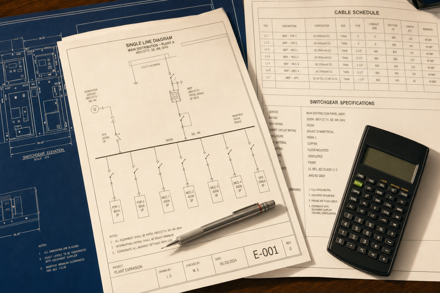
Single-line diagrams
Utility interface through the last distribution board, with fault-current annotations, protective device settings, and the emergency/standby separation clearly delineated per NEC Articles 700, 701, and 702.
Feeder and cable schedules
Every feeder documented with size, conductor material, insulation class, conduit or ductbank routing, and the ampacity calculation reference. Cable bus schedules where applicable.
Panel schedules and equipment lists
Panel schedules with calculated loads and connected loads shown separately, transformer schedules with the applied k-factor and NEMA classification, and equipment specifications keyed to the manufacturer submittals expected in construction.
Short-circuit, coordination, and arc flash
Complete study set from the utility service through the last piece of protected equipment, with the coordination narrative documenting where selective coordination is achievable and where operational judgment applies.
Specifications
Master specifications adapted to the specific project — division 26 for electrical, coordinated with divisions 27 (communications) and 28 (electronic safety and security) where the low-voltage scope is in-house. Written for the trades that will build the work.
PE-stamped drawing set
Every drawing in the set stamped by the engineer of record, signed and dated, and delivered with the design-basis document and the calculation package as a coordinated submission.
The mechanical submission package.
Load and equipment calculations
Heating and cooling load calculations per ASHRAE, ventilation calculations per ASHRAE 62.1, and pipe and duct sizing calculations documented with the applied assumptions and the design conditions used.
Mechanical drawings
Floor plans, single-line piping and ductwork diagrams, equipment schedules, and detail sheets. Coordinated with structural, electrical, and architectural drawings to catch the space and access conflicts that typically emerge in construction.
Equipment schedules and specifications
Chiller, boiler, air handler, and pump schedules with the performance data referenced to the design conditions. Division 22 (plumbing) and division 23 (HVAC) specifications written for the trades that will build the work.
Energy code compliance documentation
The energy code compliance path documented for the jurisdictional review, with envelope, HVAC, and service water heating documentation packaged for permit submission.
PE-stamped drawing set
Every mechanical drawing stamped by the mechanical engineer of record, signed and dated, and delivered coordinated with the electrical and security packages as a single submission.
The security submission package.
System narrative and design basis
The security concept of operations, the served facility risk profile, and the system architecture across access control, video, intrusion, and intercom documented as the design basis that downstream drawings trace back to.
Riser and single-line diagrams
Door-by-door access control risers, camera coverage single-lines, and intrusion zone diagrams showing head-end connections and the network pathway back to the security management system.
Device schedules and cut sheets
Device-by-device schedules for readers, cameras, contacts, and controllers with the model, mounting height, and cable-type callouts. Manufacturer cut sheets compiled for the submittal package.
Division 28 specifications
Written specifications for electronic safety and security, coordinated with division 27 (communications) and division 26 (electrical) where power and pathway are shared with the electrical package.
Coordinated drawing set
Security drawings coordinated with electrical for power and pathway, and with mechanical for ceiling coordination. Stamped by the engineer of record and delivered as part of the multi-discipline submission.
Send us the scope. We'll respond with an approach.
Every project starts with a conversation about the applicable code, the design-basis assumptions, and the constraints of the site. Send us what you have — a program document, a RFP, or a sketch on a napkin — and we'll respond with a clear approach and schedule.